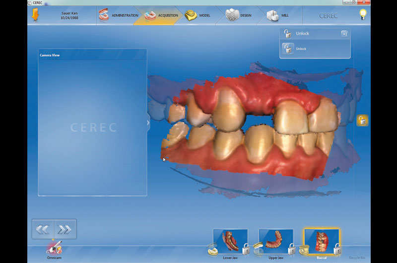
Fig. 01 Optical impressions (a digital scan) of the case were obtained by the doctor using CEREC Omnicam and CEREC 4.4 software.
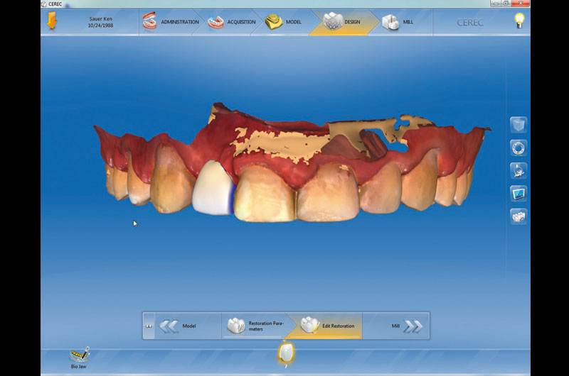
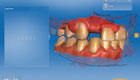
Fig. 02 A virtual tooth (digital wax-up) was designed for the patient using the CEREC 4.4 software.
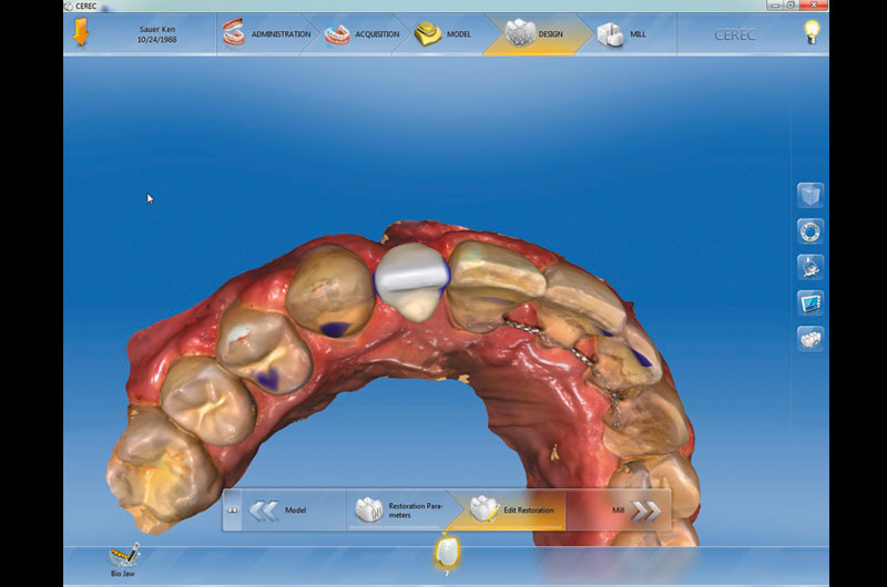
Fig. 02a A virtual tooth (digital wax-up) was designed for the patient using the CEREC 4.4 software.
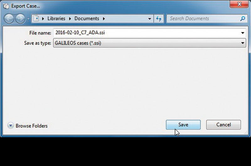
Fig. 03 The virtual wax-up design was imported as a *.ssi file and sent to the GALILEOS CBCT (cone beam computed tomography) reading workstation.

Fig. 04 The CBCT scan was acquired using Dentsply Sirona Galileos.
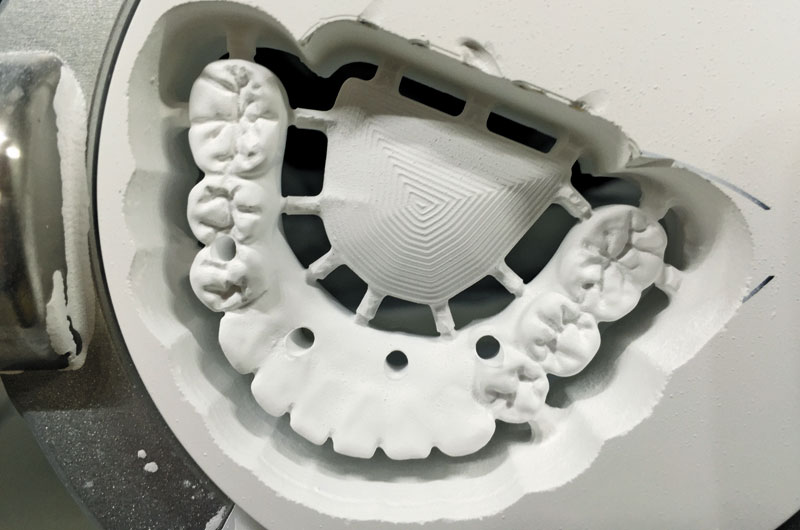
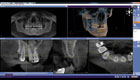
Fig. 05 The GALILEOS CBCT scan provides 3D diagnostic imaging for comprehensive dentistry and diagnostics.
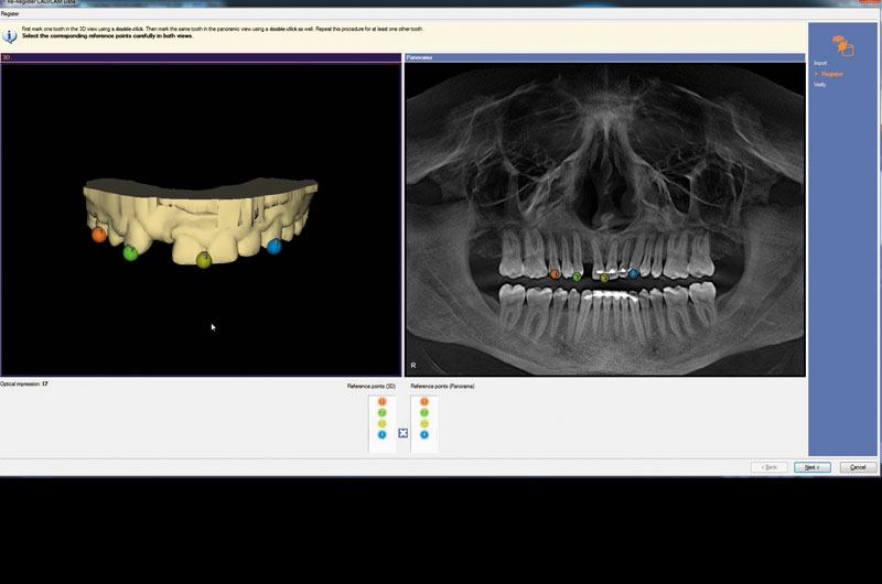
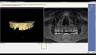
Fig. 06 The *.ssi file from the digital wax-up was integrated within the GALILEOS implant software.
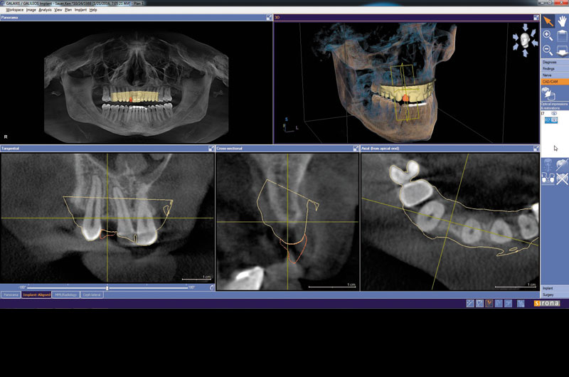

Fig. 07 The virtual wax-up was then integrated into the CBCT scan.
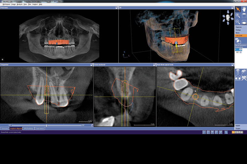
Fig. 08 Integrated implant treatment planning software allows the clinician to virtually plan implant placement in 3D.
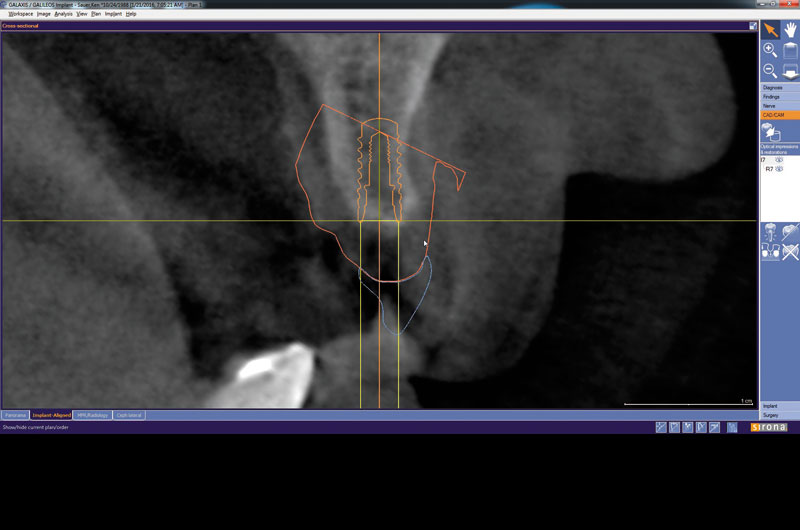
Fig. 09 A cross-sectional image showing the integrated CAD/CAM virtual restoration with the planned implant.
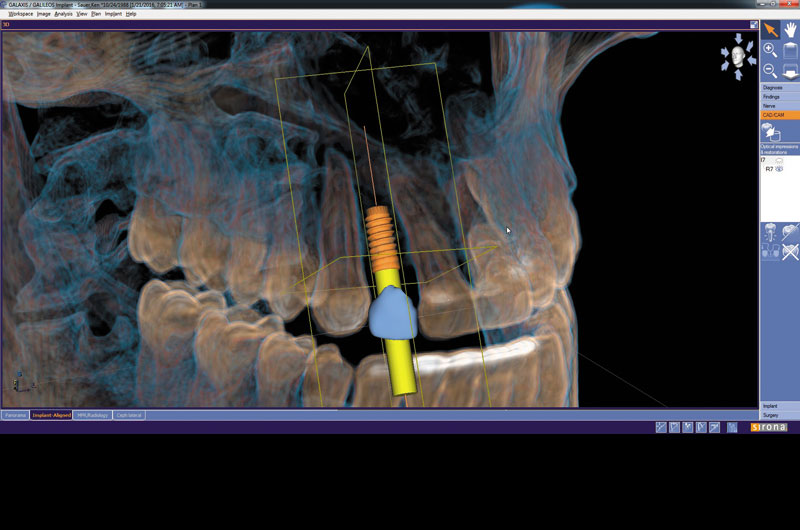
Fig. 10 A volumetric analysis of comprehensive implant planning.
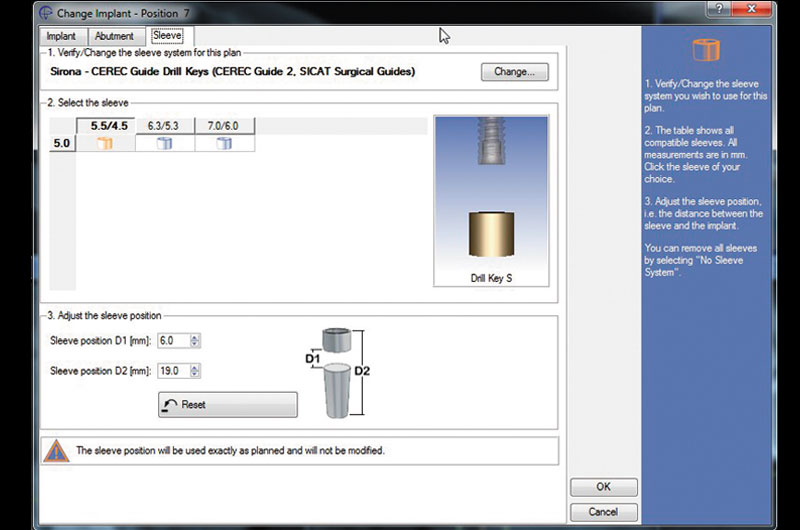
Fig. 11 The implant sleeve system was modified to the CEREC Guide 2 for guided surgery.
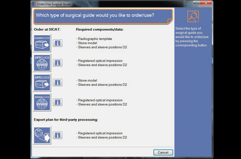
Fig. 12 A comprehensive implant plan was exported to the laboratory’s inLab SW 15 via a completely digital workflow.
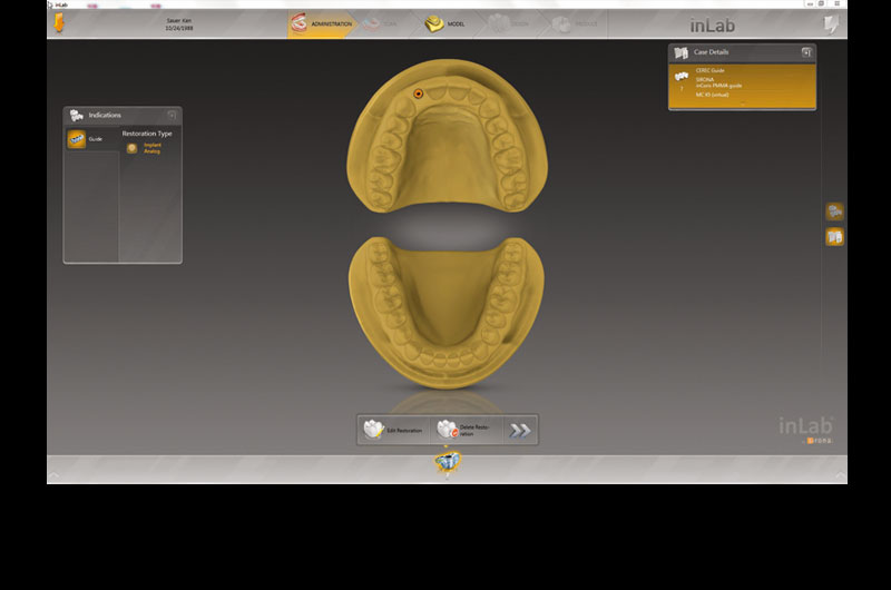
Fig. 13 A view of the inLab SW 15 importation of a comprehensive implant plan.
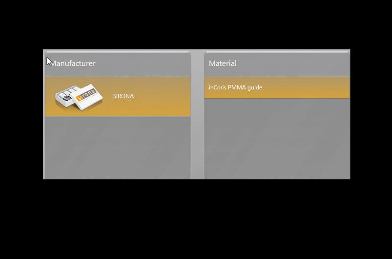
Fig. 14 The material inCoris PMMA was selected as the definitive material for the surgical guide milling.
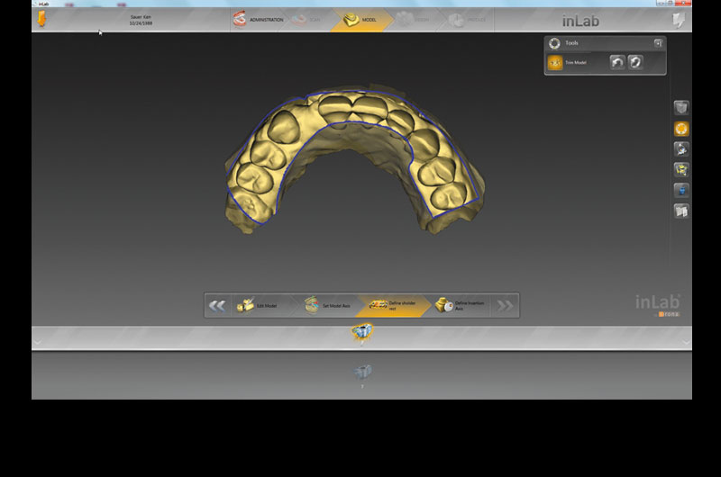
Fig. 15 The lab then trimmed the digital model for the design of the implant surgical guide directly in the software.
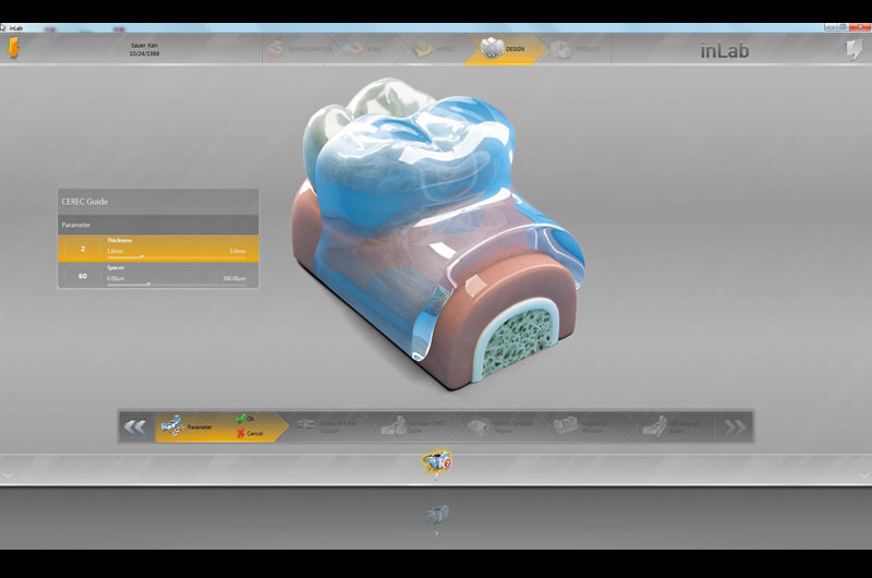
Fig. 16 Parameters were set for specific fit and thickness of the surgical guide.
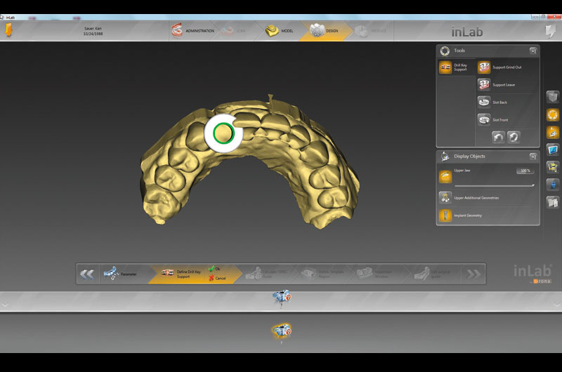
Fig. 17 Sleeve and design tools
for the surgical guide are also available to the inLab SW 15 technician.
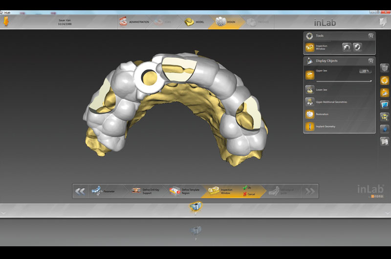
Fig. 18 An automatic proposal of the surgical guide was then displayed in the inLab SW 15 with various tools available to modify the design (i.e. addition, removal and integration of viewing windows).
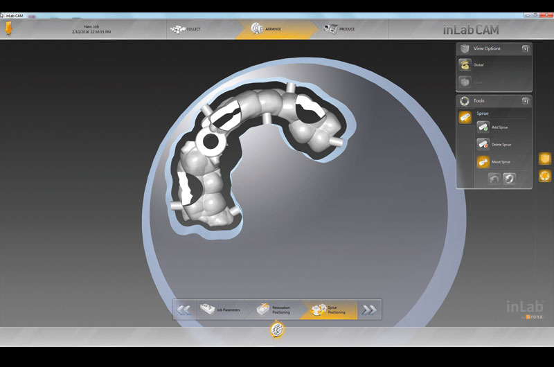

Fig. 19 Positioning of surgical guide within the inCoris PMMA material disc using inLab SW 15.
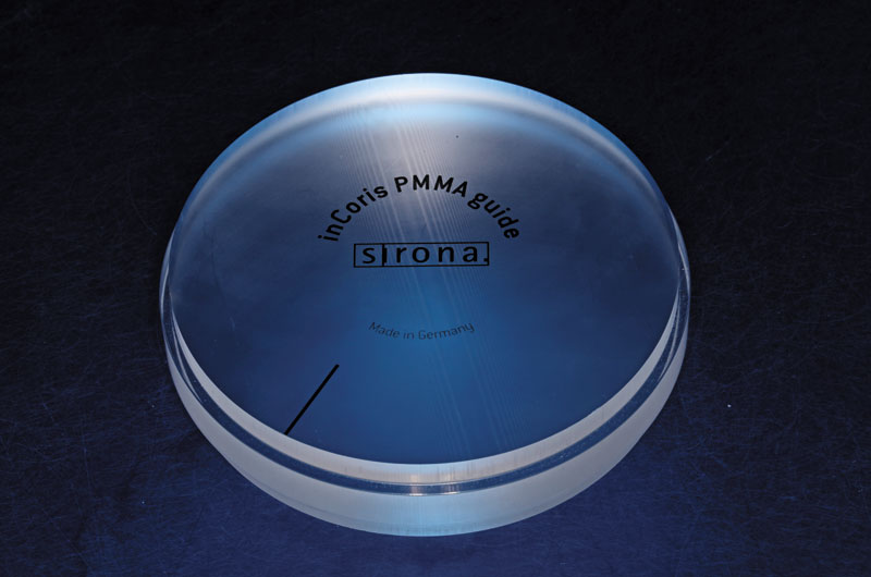
Fig. 20 A sample of the inCoris PMMA guide disc before milling.
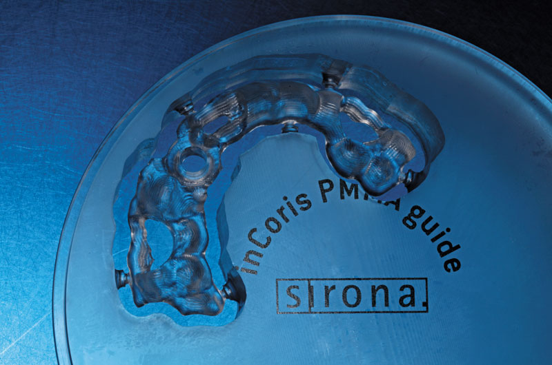
Fig. 21 The laboratory was then able to produce a completed milled surgical guide using the inLab MC X5 milling machine.
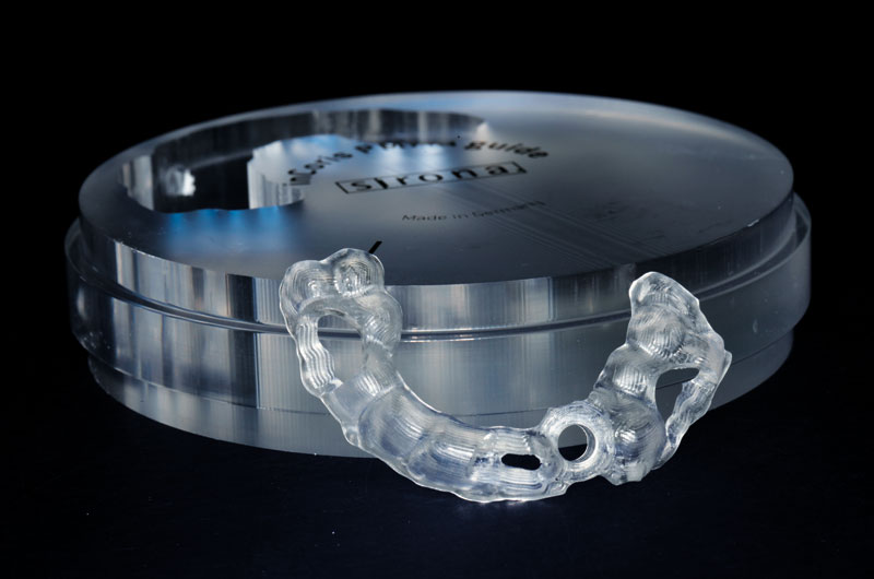

Fig. 22 Removal of surgical guide from milled disk.
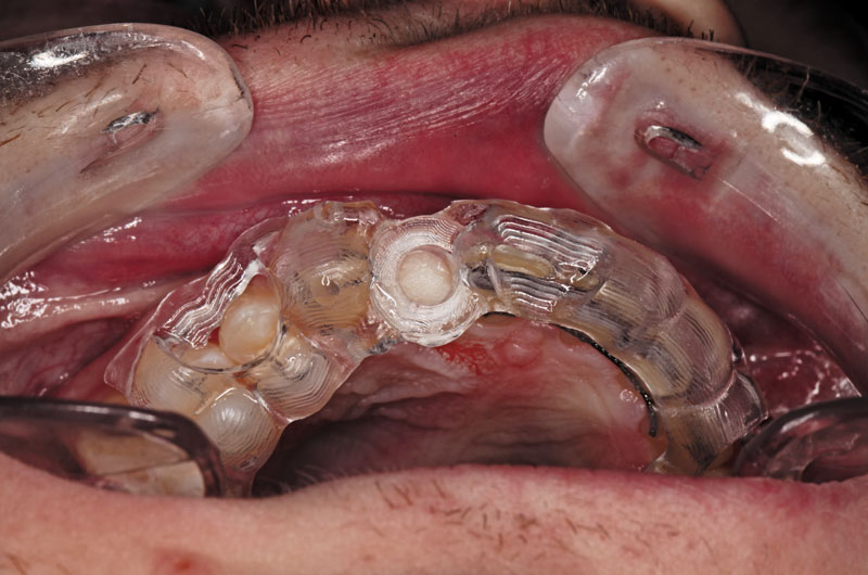

Fig. 23 The clinically seated surgical guide for guided surgery.